Hi guys. My website is normally only in italian, but this article was read more and more times (1600 times in 7 months), for this I want to translate it in english. I don’t speak english very well, for this I hope you can understand good.
Today we look at how we can use Arduino to control an external relay. But let’s start with the basics. What is a relay and why we should connect one to the Arduino?  A relay can be considered as a switch, only that instead of being activated and deactivated by our hand, is activated and deactivated by the passage of a current. A relay can be therefore used in all those cases in which a hypothetical switch must be activated by an electronic device. Let’s take a simple example. If we want to create a circuit that turns on a light at nightfall, the relay would be the right “switch” that our circuit could use to turn on or turn off the light. The same applies to the resistance of the dishwasher, the siren of the alarm, the opening of the gate of the house, etc. The first “instinct” would be to directly connect the relay to an output of Arduino: Do not do it! Let’s see why. Look at the picture here next: it’s a relay taken at random from the ones I had here at home. First of all we note that this type of relay operates at 12v (coil 12V) while the outputs of Arduino are to 5V. But be careful, there are many types of relays that operate at different voltages both lower and higher than 12V. The relay has a coil inside which the flow of current generates a magnetic field which activates the internal switch. But as it absorbs this coil? If you have the manufacturer’s datasheet you are already right. In other case
  you just need to use a multimeter and measure the ohms of coil: in my case, we are at 360 Ohm (Note: in the picture is 340 but it’s not the same relay on which I did all the calculations for the article). Since V = R * I (Ohm’s law) and so I = V / R, we get that 12V/360 ohm give me 33mA which are quite close to the maximum load of 40mA provided by the Arduino’s output pins. But when we design circuits of this type, have to use a so-called “protection factor 2” on outputs of the integrated . For this we should ask ourselves to take not more than 20mA from the outputs of the Arduino, which is half of the maximum output power. How we can do it? The solution is relatively simple: use a transistor! Do not run away, wait a minute, is not so hard. In the picture you can see a set of transistors near ready to use. Even if you do not know them, you can just buy for few Euros one of these kits where you find 100, among the most common types. But now that we know that your purchase is not particularly problematic, how we have to connect the transistor to Arduino? Basically a transistor is usable as an amplifier, so we can increase the weak Arduino’s
  signal to a stronger one, sufficient to switch on a relay. I’m not speaking about miracles outside the physical law, the increased power comes from a external 12V line. Nearby you can see the representation of the circuit diagram. As you can see the transistor (Q1) consists of 3 pins that are called emitter, base and collector. The arrangement of the three-pin is not the same in all the transistors so we have to look to recognize with certainty the scheme provided by the manufacturer. However in all cases we have to connect the base to the “weak” Arduino’s output , while the stronger current that trigger the relay will flow from the collector to the emitter. Summing up: We need a transistor that the base will have to operate at 5V with a maximum of
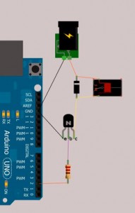 20mA and that in these conditions allow to pass a current between the collector and emitter of 12V / 33mA. Another fundamental thing is the diode in series with the relay. This is crucial to protect the transistor.
When in fact we close the circuit, the relay coil creates a magnetic field that allows triggers the internal switch. Then, when, we re-open the circuit, the transistor will be closed to the passage of the coil current, BUT the current will continue to pass due to induction from the magnetic field. This result to a current peak which can burn easily the transistor. The diode serves precisely to ensure that the current can be discharged without damage. Now, the question is: Now the question is: how we choose the transistor? Turning the box to find all the technical data we need. This does not mean that we are obliged to bought the same package that among other I bought at random. The important thing is to know what information we need and if you haven’t the datasheet Google is your better friend. We’re going to get one of the NPN and not a PNP (the difference is in the polarity).
If we take the BC547B, one of the numerous in the box, we see that the collector supports a maximum of 45V (Vce), quite sufficient to withstand the required 12V from the relay. The maximum peak current to the collector is 200mA (Ic max = 0.2A) against only 33mA necessary to power the relay. Now we have to properly size the resistance located between the output of Arduino and the base of the transistor. If current relay is 33mA and the hFE of the transistor is 200 we obtain a minimum value of current at the base of 33/200 = 0.165mA but for a variety of reasons related to the nature of the transistors must be multiplied by at least 2 or 3 times coming to 0.33-0.495mA (~ 0.5mA). Therefore, the current at the base of the transistor must be of a minimum of 0.5mA and a maximum of 20mA (half of what can be deliver by Arduino). Knowing this we can easily calculate the value of the resistance. We know that the voltage of Arduino’s output pin is 5V but it must be reduced to 0.7V absorbed by the transistor. Therefor we have 4.3V with resistance values between 4.3/0.5 and 3.4/20 that, after a simple conversion of units, give a value between a minimum resistance value of 215 ohms and a maximum of 8600.
We just have to prepare the circuit and create a small software for testing. Clearly a resistance value between the highest will use a smaller current (from Arduino), which is preferable. I used in the test an intermediate value of 4.7K (4700 ohm). Now that you know how do all calculation, please visit this page: it’s aonline specific calculator for choosing the right resistence. It’s in Italian but you can use without speaking that language. For the software we can simply use the example above that makes the internal LED flash, just use exit 13 because in addition to flash the LED there is also the opening and closing of the relay. Be careful that in the scheme of the circuit the collector and emitter are reversed from the reality of the project, but as I said the location is not standardized. I leave you a picture of the project you can see even at full resolution clicking on it and with a video where you can hear the “click” of the relay. You will also notice the external 12V power supply.
The green crocodile is only to take together the wire to the relay. The flicker of relay click is for the unstable connection between wires. Sorry for the imperfect synchronization from audio and video.

No Responses to “Arduino: connect a 12V relay (english version)”